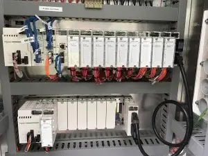
This article explains the Steps in PLC System Design and outlines the key considerations for developing a reliable and efficient control system. Programmable Logic Controllers (PLCs) are fundamental components of industrial automation and operate at Level 1 (L1) of the automation hierarchy. At this level, the PLC interfaces directly with field devices, processes input/output (I/O) signals, and executes programmed logic to control industrial operations.
PLCs form the foundation for higher-level systems such as SCADA, cloud platforms, and Industrial IoT applications. These systems rely on accurate field data and control actions generated by the PLC. Without a properly designed control system, communication between field devices and higher automation layers can become unstable or inefficient.
For this reason, careful planning, appropriate hardware selection, environmental assessment, safety evaluation, and structured programming are essential. Several technical factors must be reviewed before selecting and implementing a PLC system to ensure long-term reliability, safety, and scalability.
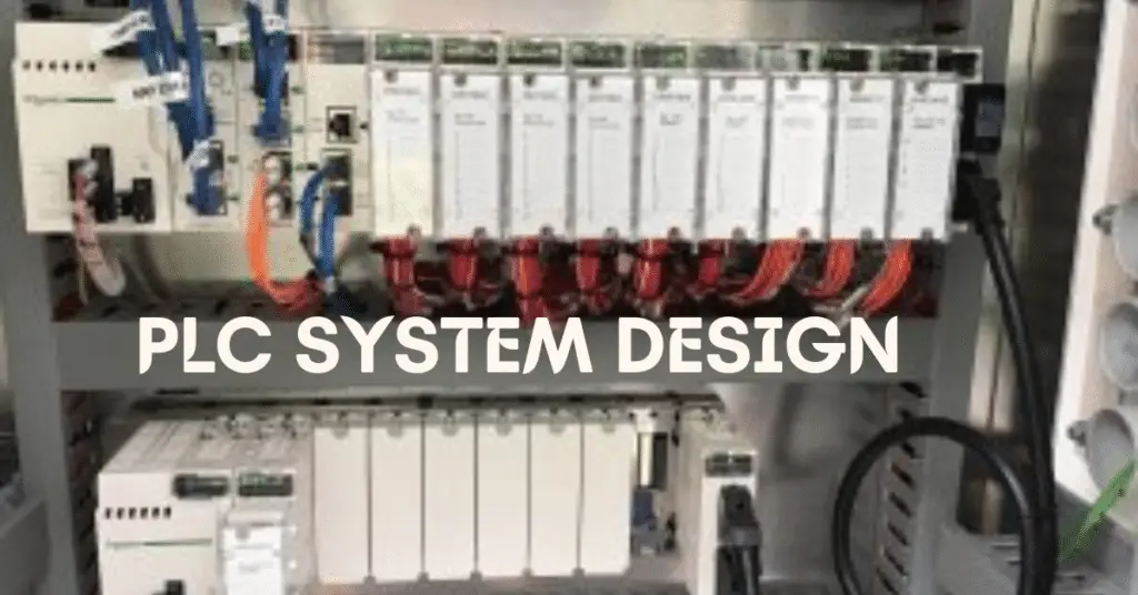
PLC System Design
Some common steps that are crucial for designing of PLC are:
- The Environmental Specifications
- The Grounding and Earthing
- Safety
- The Networking
- Field Devices and the IO count
- Proper Grouping of Devices
- Field Wiring Voltage Levels
- Program Complexity and Redundancy
- HMI Integration
- Maintenance and Documentation
Now, we will discuss the Steps in PLC System Design.
1. Environmental Specifications
All electrical devices have some amount of environmental design constraint. The PLCs are also a type of electronic device and PLC components are very sensitive to environmental effects. So, it is important to see that no damage is caused because of any abnormal surrounding effect. The PLC must be able to perform functions that are mentioned in the catalog.
Some basic environmental factors which need to be considered are ambient temperature (during operation and storage), relative humidity, operating altitude, and mechanical stress for example vibrations.
The PLC installed should meet the nearby environmental specifications. When the temperature is outside the operating range whether extremely hot or cold, it is advised to use a hard-rugged PLC that would meet the given specifications. Some supporting equipment like fans, air conditioners, heaters, etc can be used when using PLC in such an environment.
In addition, electromagnetic interference (EMI) from nearby drives, motors, or switching devices must be considered. Proper cable shielding and segregation of power and signal wiring help prevent malfunction due to electrical noise.
The enclosure IP rating should also be selected based on whether the installation is indoor, outdoor, dusty, or located in a hazardous area.
2. Grounding and Earthing
Grounding and earthing are crucial aspects of designing a PLC system. If there is improper grounding, it can result in physical hazards, electrical equipment damage, and life loss. In a PLC, there are grounding points in the power supply and input-output terminals. During the installation of the PLC panel, it is important to ensure that the ground is connected at each and every point available.
There are two types of earthing in a PLC panel. They are instrument earth and power earth. The PLC input and output card should be connected to the instrument earthing. They should not be connected to power earthing. It must be noted that the voltage between earthing and neutral should always be less than 0.5V.
Star grounding techniques are often recommended to avoid ground loops, especially for analog signals such as 4–20 mA. Ground resistance testing should be conducted during commissioning to verify proper grounding performance.
3. Safety Concerns
The safety concern is very paramount in PLC system design. In an industry, a PLC will deal with many critical field devices. Hence it is very important to look at the safety aspect. The PLC must be programmed in such a way that digital outputs must be assigned for a hooter, fault lamp, tower lamp, and buzzer. This will alarm the operator whenever there is a fault.
It is advised to have the safety review at the actual site to check whether it can be impacted by any mechanical, environmental, thermal, electrical, or chemical hazard or not.
Safety PLCs are also available. These have safety integrity level functionalities that deal with different types of IO safety and programming safety. They can detect permutations and combinations of failures to safely shut down the system.
Also, based on the process criticality, different PLCs with different scan times are available.
For critical applications, compliance with international safety standards such as IEC 61508 or ISO 13849 should be considered. Redundant CPUs and fail-safe IO modules may be implemented in high-risk processes to enhance operational safety.
4. Networking
A PLC needs to deal with external communications with third-party or same-party devices at some other point. For communication to provide more flexibility in dealing with data, we use many protocols in communication with field devices, for example, SCADA. Therefore, networking
The communication can be sensitive to noise or some other electrical disturbances, it is thus important to properly choose the cable with shielding. In an Ethernet protocol, it is recommended to provide an Ethernet hub switch in the panel, whether managed or unmanaged. This is done so that many people can use data from it.
Common industrial communication protocols include Modbus TCP/IP, PROFINET, Ethernet/IP, and Profibus. The selection of protocol depends on compatibility, speed, and system architecture.
Cybersecurity measures such as strong password policies, VLAN segmentation, and firewall protection should be implemented to prevent unauthorized access to PLC systems.
5. Field Devices and IO Count
When a PLC is chosen, the number of IOs and field instrument types are already taken into consideration. The proper knowledge of voltage and current is required for working with field devices. Based on this, the required PLC and cabling length are decided. It must be noted that it is always advisable to consider a minimum of 20% spare in IO counts. This gives flexibility in case of end-time additions in IOs.
https://www.electricalvolt.com/noise-in-electronic-systems-and-types-of-noise/In case the distance between PLC and the field device is more or if the PLC would be installed in a hazardous area, then barriers and isolators are also installed within the panel. In the case of analog IOs, properly shielded cables are used because they are more prone to noise.
For large installations, remote IO systems connected via fieldbus networks can significantly reduce wiring complexity and installation cost.
6. Grouping of Devices
In a PLC, a proper grouping of devices is done according to the voltage level in the PLC panel during design. This will make sure that the AC and DC devices are grouped separately, for example, circuit breakers, relays, terminal boards, power supplies, and transformers.
It is advised to keep these groups separate and not mix them. Also, the circuit breaker must not be kept near the PLC. It is better to keep isolation between the devices of the same voltage level.
Thus, troubleshooting will be easier, and unwanted performance and noise in the panel can be reduced. When an AC and DC device are separated and grouped, the panel looks more attractive. It also becomes easier to identify each and every device properly.
Clear labeling, proper wire numbering, and logical cable routing further enhance maintainability and reduce troubleshooting time.
7. Voltage Level Based Field Wiring
In a PLC panel, both AC and DC voltages co-exist. When a particular field device is powered by a separate power source, it must be ensured to use the common point for working with it. Care must be taken so that the unwanted common field signals do get mixed, otherwise, they can damage the PLC or the field device.
Analog signal cables should preferably be twisted pair and shielded, with the shield grounded at one end only to prevent ground loop issues.
8. PLC Program Complexity and Redundancy
The redundancy factor must be taken into consideration when designing a PLC. The PLC must be chosen accordingly. Also, the PLC should be able to perform the task in the required scan time, memory, and redundancy.
The PLC scan cycle time should be evaluated during the design stage to ensure real-time process requirements are met. For critical systems, redundant power supplies and communication modules may be added to prevent downtime.
9. HMI Integration
Human Machine Interface (HMI) systems provide real-time monitoring and control of PLC operations. Through an HMI, operators can adjust timer values, monitor alarms, view trends, and diagnose faults without directly accessing the PLC software.
Proper HMI design improves operator efficiency and reduces human error.
10. Maintenance and Documentation
Routine maintenance ensures long-term reliability of PLC systems. Panels should be kept clean and free from dust accumulation. All terminal connections must be periodically checked and tightened according to manufacturer torque specifications.
Complete documentation including network IP addresses, PLC program version, IO list, and wiring diagrams should be stored inside the panel for quick reference during troubleshooting.
PLC Programming Basics
The CPU of PLC will execute two different programs. They are:
- Operating system
- User program
Operating System
The operating system performs the function of organizing the entire functions, operations, and sequences of the CPU that are not associated with a control task. Some tasks of an operating system include:
- Handling of a hot restart and a warm restart
- Updating and outputting the process image tablets of input and outputs
- Execute the user program
- Detect and call the interrupts
- Manage the memory areas
- Establishes communication of programmable devices
User program
The user program is a combination of many functions that are required to process an automated task. This should be created by the user and must be downloaded to the CPU of the PLC. The user program performs the following tasks:
- Initialization of all conditions in starting the specified task.
- The reading and evaluation of all binary and analog input signals.
- The specifying output signals to all binary and analog output signals.
- The execution of interrupts and handling errors
There are many PLCs that range from small to high-end PLCs. All PLC manufacturers have their own dedicated software to program and configure the PLC hardware. The PLC programming language varies depending on the manufacturers. Some of these manufacturers have common programming languages and some have different languages. These languages are of two types. They are:
- Textual language
- Instruction List (IL)
- Structured Text (ST)
- Graphical Language
- Ladder Diagrams (LD)
- Function Block Diagrams (FBD)
- Sequential Function Chart (SFC)
The graphical languages are preferred in comparison to the text languages for programming a PLC because they are having simple and convenient programming features. There are some necessary functions and functional blocks which are present in the standard library of all PLC software. There are timers and counters, comparators, strings; numeric, arithmetic, bit-shift and calling functions, etc. in the functional blocks.
This is all about the PLC system design.
Read Next: