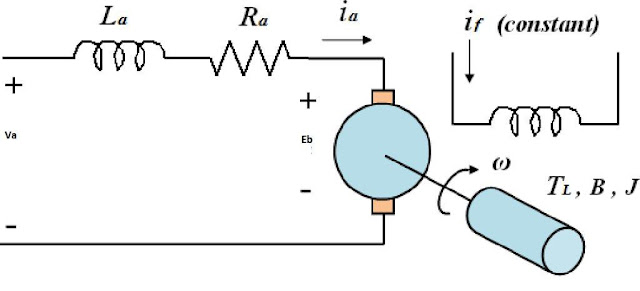
IR compensation method is used to provide the speed regulation in the DC drive. The DC drive increases the output voltage of the drive to maintain the speed of the drive. The block diagram of the separately excited DC motor is given below.
In a DC drive, the speed of the DC motor is governed by regulating the DC voltage by controlling the firing angle of the SCRs.
The speed of the DC motor can be given with the following formula.
N=K * Eb /ø = K*( V-Ia* Ra)/ø —–(i)
Where,
N = Speed of the motor,
Eb= Back EMF of motor
Ra= Armature Resistance
Ø= Field Flux
In a separately excited DC motor, the field flux is kept constant.

The speed of the DC motor is governed by controlling the armature voltage. The DC drive controls the DC output voltage fed to the DC motor. However, as per equation (1), the speed of the motor is not exactly proportional to the armature voltage; the speed of the motor is proportional to the motor’s back EMF, which is equal to (V- Ia*Ra).
In precise speed control applications like in the weighing system, the RPM of the motor is controlled in the close loop to ensure the desired speed accurately. The motor speed can be measured with a tachometer mounted on the motor shaft that accurately measures the speed.
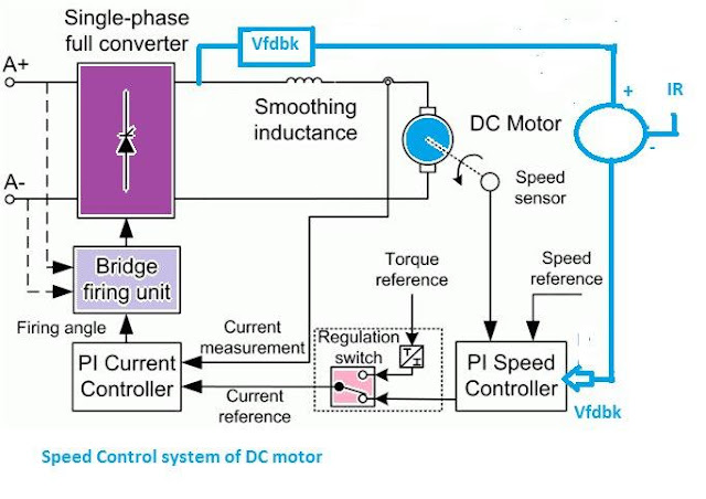
The control scheme of the DC motor with speed feedback arrangement is given below.

The speed control of the DC motor can be achieved by controlling the armature voltage by changing the firing angles of silicon control rectifiers (SCRs). The speed of the motor can be measured with the tachometer mounted on the motor shaft or by measuring the armature voltage of the motor.
The measurement with the tachometer gives an accurate measurement of the motor speed. The speed measured through the tachometer is compared with the desired speed reference, and the resultant error signal controls the firing angles of the SCRs.
When the drive runs on tachometer feedback, IR compensation is not required as the drive increases voltage as per the set point of speed.
If the tachometer voltage feedback circuit fails, the drive system can be smoothly changed from a tachometer to an armature voltage feedback system. The armature voltage feedback as a speed feedback signal is the derived parameter for speed measurement of the DC motor; it does not give the accurate speed of the motor.
The measurement error, as stated above, is because the speed of the motor is directly proportional to the back EMF. The back EMF of the DC motor can be calculated by subtracting the armature resistance drop (Ia*Ra) from the armature applied voltage.
The DC drive calculates the IR drop of the motor from the mathematical algorithm stored in its microprocessor. When the motor is first commissioned, the drive must be auto-tuned with the DC drive controller—the drive stores all-important motor parameters during the auto-tuning process.
When the motor speed control feedback is changed from tachometer to armature voltage, the drive calculates the IR drop of the armature, and the firing angle of the SCRs is reduced to increase the armature voltage to compensate for the IR drop of the armature. When the drive takes armature voltage as speed feedback, the IR compensation is a must to get the desired motor speed.