Dive into the fundamentals of Gunn Diode Oscillators, their construction, operation, and applications in microwave technology.
What is a Gunn Diode Oscillator?
A Gunn Diode Oscillator is a cost-effective source of microwave power. It is also known as a Gunn oscillator or Transferred Electron Device (TED) oscillator. It has Gunn diode (TED) as its core component and functions similarly to Reflex Klystron Oscillators.
In a Gunn oscillator, the Gunn diode is placed inside a resonant cavity, where it generates microwave oscillations due to the Gunn effect. The oscillator has two main components:
- DC Bias – Provides the required power.
- Tuning Circuit – Adjusts the oscillation frequency.
Gunn diode oscillators are widely used in radar systems, microwave communication, and industrial heating applications due to their high-frequency stability, compact size, and cost-effectiveness. Unlike other microwave sources, they do not require complex external frequency stabilization components, making them an efficient choice for many applications.
How a Gunn Diode Works as an Oscillator
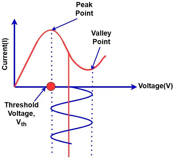
When a DC bias is applied to a Gunn diode, the current initially increases with voltage. However, once it reaches a certain threshold voltage, an unusual behavior occurs:
- Instead of continuing to rise, the current decreases as voltage increases beyond this point, up to the breakdown voltage.
- This phenomenon creates a negative resistance region, which causes oscillation.
The presence of negative resistance allows the diode to sustain continuous oscillations, making it a key component in microwave signal generation.
The negative resistance characteristic of a Gunn diode sustain oscillations by offsetting circuit losses, allowing a continuous flow of current. When positioned inside a resonant cavity, the diode naturally produces high-frequency microwave oscillations due to the Gunn effect. As long as a DC bias is applied, these oscillations persist, with their amplitude remaining stable within the negative resistance region, ensuring efficient and consistent signal generation.
Frequency Control and Tuning in Gunn Diode Oscillators
The oscillation frequency of a Gunn diode oscillator is primarily influenced by the active region of the Gunn diode. However, the resonant frequency can be adjusted externally through mechanical or electronic tuning methods, making it adaptable for various applications.
Electronic Tuning Methods
For precise frequency control, electronic tuning is achieved using components such as:
- Waveguides – Guide and confine microwave signals.
- Microwave Cavities – Provide resonance for stable oscillations.
- Varactor Diodes – Offer voltage-controlled frequency variation.
- YIG (Yttrium Iron Garnet) Spheres – Provide highly stable and tunable frequencies under a magnetic field.
These tuning techniques enable fine frequency adjustments, making Gunn oscillators ideal for applications demanding stable and tunable microwave signals, such as radar systems and communication devices.
Mechanical Tuning in Gunn Oscillators
In a Gunn diode oscillator, the diode is housed within a resonant cavity, which helps cancel out circuit losses and sustain oscillations. Mechanical tuning modifies the cavity’s physical dimensions or adjusts the magnetic field (in YIG spheres) using an adjustment screw or other mechanical components.
Microwave Frequency Range and Design Variations
Gunn diode oscillators can generate microwave frequencies ranging from 10 GHz to several THz, depending on the cavity’s dimensions. Different designs affect power efficiency and frequency stability:
- Coaxial and Microstrip/Planar Designs – Compact but sensitive to temperature variations, leading to lower power efficiency.
- Waveguide and Dielectric Resonator Designs – Offer higher power output and superior thermal stability, making them suitable for demanding applications.
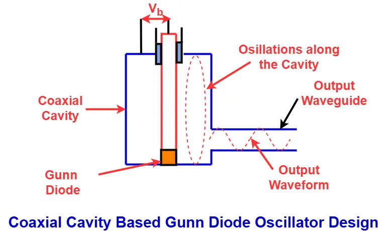
For example, coaxial resonator-based Gunn oscillators operate between 5 GHz and 65 GHz. When a voltage (Vb) is applied, Gunn diode-induced fluctuations travel within the cavity, reflect from the opposite end, and return in time (t). This time period depends on the cavity’s physical properties and directly influences oscillator performance.
The time period (t) can be calculated using: t=2l/c
Where:
- l = cavity length
- c = speed of light
The resonant frequency (f) of a Gunn oscillator is given by: f=nc/2l
Where:
- n = number of half-wavelengths fitting inside the cavity
This equation indicates that smaller cavities result in higher frequencies, allowing for precise frequency control in Gunn diode oscillators.
Oscillations in a Gunn diode oscillator begin when the resonator loading slightly exceeds the maximum negative resistance of the diode. As the oscillations grow, their amplitude increases until the average negative resistance balances the resonator’s resistance, ensuring sustained oscillations.
To prevent burnout from high-amplitude signals, a large capacitor is used to stabilize voltage levels and protect the diode from excessive power dissipation.
Applications of Gunn Diode Oscillators
Due to their high-frequency stability, compact design, and tunability, Gunn diode oscillators are widely used in various fields, including:
- Radio transmitters – Provide stable microwave signal generation.
- Radar sources – Used in Doppler and speed detection radars.
- Velocity sensors – They measure speed in industrial and scientific applications.
- Parametric amplifiers – Enhance weak microwave signals.
- Motion detectors – Used in security and automation systems.
Read Next: