Discover the key differences between the firing angle and conduction angle of an SCR (Silicon Controlled Rectifier). Learn how these parameters influence the control and performance of SCRs in AC circuits, including definitions, measurements, control aspects, ranges, purposes, and their relationship. Understand how adjusting the firing angle impacts the conduction angle and the power delivered to the load.
The firing angle and the conduction angle of an SCR (Silicon Controlled Rectifier) are two distinct parameters that define its operation in an AC circuit. Here’s a detailed explanation of the differences between the two:
Firing Angle (α) of SCR
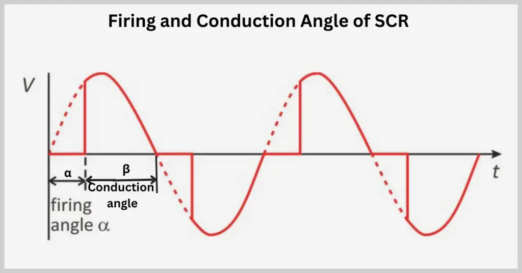
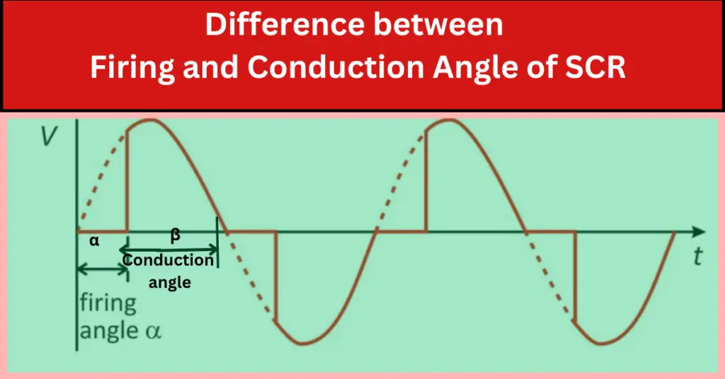
- Definition: The firing angle is the angle at which the gate signal is applied to the SCR to turn it on within each AC cycle. It is measured from the zero-crossing point of the AC voltage waveform.
- Control: The firing angle is a control parameter that regulates when the SCR starts conducting within each half-cycle. By adjusting the firing angle, you can control the portion of the AC waveform during which the SCR conducts.
- Range: The firing angle typically ranges from 0° to 180° in each half-cycle of the AC waveform.
- Purpose: It controls the output voltage and power delivered to the load. A smaller firing angle means the SCR turns on earlier, resulting in higher power delivery. In comparison, a larger firing angle means the SCR turns on later, resulting in lower power delivery.
Conduction Angle (β) of SCR
- Definition: The conduction angle is when the SCR remains conducting within each AC half-cycle. It is measured from where the SCR starts conducting to the end of the half-cycle.
- Relationship with Firing Angle: The conduction angle complements the firing angle and can be calculated as β=180∘−α, where α is the firing angle.
- Duration: The conduction angle represents the duration the SCR conducts current in each half-cycle. The firing angle directly influences it.
- Purpose: It defines the portion of the AC waveform during which the SCR allows current to pass through. The conduction angle determines the average power delivered to the load.
Comparison of Firing Angle and Conduction Angle
- Measurement:
- Firing Angle (α): Measured from the zero-crossing point of the AC waveform to the point where the gate signal is applied.
- Conduction Angle (β): Measured from the point where the SCR starts conducting to the end of the half-cycle.
- Control and Effect:
- Firing Angle (α): Controlled externally to regulate when the SCR turns on. Affects the conduction angle and the power delivered to the load.
- Conduction Angle (β): This depends on the firing angle and affects the duration of the current flow and the resulting power delivery.
- Relationship:
- The conduction angle is directly related to the firing angle by the equation β=180∘−α
Example- Firing & Conduction Angle
Consider an AC half-cycle:
- Firing Angle α=60∘
- The SCR is triggered at 60° after the zero-crossing point.
- The conduction angle β=180∘−60∘=120∘
- The SCR conducts for 120° of the half-cycle.
- Firing Angle α=120∘
- The SCR is triggered 120° after the zero-crossing point.
- The conduction angle β=180∘−120∘=60∘
- The SCR conducts for 60° of the half-cycle.
Adjusting the firing angle and conduction angle can thus precisely control the amount of power delivered to the load.
Example Values
| Example Firing Angle (α) | Resulting Conduction Angle (β) | Description |
| 0° | 180° | SCR conducts for the entire half-cycle. |
| 60° | 120° | SCR conducts for 120° of the half-cycle. |
| 90° | 90° | SCR conducts for half of the half-cycle. |
| 120° | 60° | SCR conducts for 60° of the half-cycle. |
| 180° | 0° | SCR does not conduct at all. |
Difference between Firing and Conduction Angle
| Parameter | Firing Angle (α) | Conduction Angle (β) |
| Definition | The angle at which the gate signal is applied to the SCR to turn it on within each AC cycle. | The angle during which the SCR remains in the conducting state within each AC half-cycle. |
| Measurement | Measured from the zero-crossing point of the AC voltage waveform to the point where the gate signal is applied. | Measured from the point where the SCR starts conducting to the end of the half-cycle. |
| Control | Controlled externally to regulate when the SCR turns on. | Depends on the firing angle. |
| Range | 0° to 180° in each half-cycle of the AC waveform. | 0° to 180° in each half-cycle of the AC waveform. |
| Purpose | To control the output voltage and power delivered to the load. | To define the portion of the AC waveform during which the SCR allows current to pass through. |
| Relationship | Directly set by the user. | Calculated as β=180∘−α |
| Effect | Affects the conduction angle and the power delivered to the load. | Determines the average power delivered to the load. |
Related Articles: