Light dependent resistor LDR or photoresistor changes its resistance when light falls on it, thus it detects the presence of light.
In this article, we will learn about Light dependent resistors (LDR or photoresistors), their symbol, construction, working, types, latency, technical specifications, and applications of LDR.
What is a Light Dependent Resistor (LDR)?
A Light Dependent Resistor (LDR) is known by different names. It is also called a photoresistor, photocell, photoconductor, or photoconductive cell. The resistance of an LDR changes based on the amount of light falling on it. Its sensitivity depends on the wavelength of the incident light. Since it responds to light, it is a light-sensitive device. It is mainly used in circuits to detect the presence and level of light.
It is made of semiconductor material, and its resistance decreases when the intensity of light hitting on it increases. Ultimately, its resistance is more when the intensity of light is less.
LDR / Photoresistor Symbol
The LDR symbol in electronic circuits is based on the resistor symbol. However, it also includes arrows to show light shining on it. Similarly, this follows the same pattern as photodiode and phototransistor symbols. In these symbols, arrows indicate light falling on the components.
The light-dependent resistor (LDR) or photoresistor circuit symbols are shown in two styles. First, the newer style uses a rectangular box as the resistor symbol. The older style represents the resistor with a zig-zag line.
Often, the light-dependent resistor (LDR) symbol is shown without a circle around it. This is usually done in electronic circuit schematics to save space. Additionally, it reduces the number of lines and circles in the diagram. As a result, the schematic becomes less complicated.
The most commonly used symbols of the light-dependent resistor (LDR) are shown in the following figure.
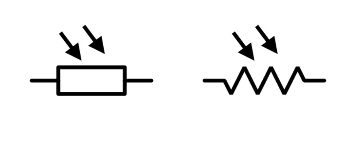
The arrows in the LDR symbol represent light falling on it.
Construction of Light Dependent Resistors (LDR)
LDR is made from semiconductor materials that have a property called photoconductivity. LDR is made from semiconductor materials such as lead sulfide (PbS), Indium antimonide(InSb), Cadmium Selenide(CdSe), and cadmium sulfide (CdS). The most common semiconductor material used for making the LDR is Cadmium Sulfide (CdS ) and Cadmium Selenide(CdSe).
However, the use of Cadmium Sulfide(CDS) and Cadmium Selenide(CdSe) is now restricted in Europe due to environmental concerns related to cadmium. Therefore, alternative materials including lead sulfide (PbS) and indium antimonide (InSb) can be used.
Although LDR/photoresistors are made from semiconductor materials, they are passive devices. This is because they do not have a PN junction. This distinguishes them from other photodetectors, such as photodiodes and phototransistors.
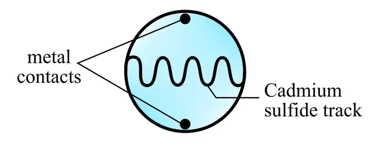
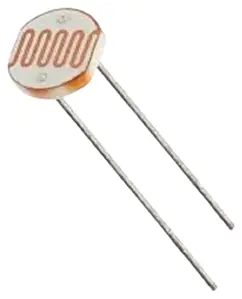
- The core of LDR is made of semiconductor material like Cadmium Sulfide.
- The semiconductor material is directly linked with two metal electrodes to allow the current through the LDR.
- LDR is placed in the protective casing to protect it from external factors such as dust, moisture, and physical damage.
- When there is no light, the resistance is very high, reaching Mega Ohms. When light falls on it, the resistance decreases, and conductivity increases.
Working of Light Dependent Resistors (LDR)
It works on the principle of photoconductivity. When the LDR is in darkness or low light conditions, its resistance is very high, often in the range of megaohms (MΩ). This high resistance occurs because the semiconductor material has very few free electrons available to conduct electricity. In the absence of light, electrons in the semiconductor are tightly bound to atoms and cannot move freely, which limits the flow of electrical current.
When light falls on the LDR, the covalent bonds break, creating free electrons and holes. These charge carriers gain energy and move from the valence band to the conduction band, allowing current to flow. As the incident light increases, the resistance of the LDR decreases. More light generates more charge carriers, decreasing resistivity.
As a result, its resistance decreases when the intensity of light hitting increases. Ultimately, its resistance increases when the intensity of light is less because the formation of free electrons is less.
The more intense the light, the more electrons are freed, and it lowers the LDR resistance. This relationship between light intensity and resistance is generally inverse; as light intensity increases, resistance decreases.
Types of Light Dependent Resistors (LDR)
There are two types of Light-dependent resistors as shown in the following:
- Intrinsic LDR
- Extrinsic LDR
1). Intrinsic LDR:
This type of photoconductive cell or LDR is made of pure semiconductor material like Silicon or Germanium. There is no doping with the impurities. When light falls on it, electrons get sufficient energy and come into the conduction band and when the number of electrons increases in high intensity of light, the resistance will be less.
In such a material, the number of charge carriers is solely determined by the thermal excitation, and electrical conductivity is relatively low.
2). Extrinsic LDR:
This type of photoconductive cell or LDR is made of semiconductor material like Silicon or Germanium and doped material. There is doping with the impurities. When light falls on it, electrons need less energy and come into the conduction band. When the number of electrons increases with the high light intensity, the resistance will be less. In extrinsic LDR, the addition of impurities causes a reduction in the band gap between the valance and conduction band, and thus, electrons need less energy. As a result, electrons enter into the conduction band even in the low intensity of light.
Extrinsic LDR is more sensitive to light because, here, electrons enter into the conduction band even in the presence of low-energy photons.
The table below lists the common materials used for intrinsic and extrinsic photoresistors and their spectral response ranges.
| Material | Type | Spectral Response Range (nm) |
|---|---|---|
| Silicon | Intrinsic | 190 – 1100 |
| Germanium | Intrinsic | 400 – 1800 |
| Cadmium Sulfide (CdS) | Extrinsic | 320 – 1050 |
| Cadmium Selenide (CdSe) | Extrinsic | 350 – 1450 |
| Lead Sulfide (PbS) | Extrinsic | 1000 – 3500 |
| Lead Selenide (PbSe) | Extrinsic | 1500 – 5000 |
Limitation of LDR
LDRs have certain limitations in terms of latency and frequency dependency. Let us discuss these terms.
Latency of LDR
The term Latency refers to the delay between input signal and output response. LDRs do not have significant latency. It is also called Response time.
The response time or latency of LDR mainly depends upon the physical properties of semiconductor material and the design of the LDR circuit. LDRs are relatively slow in response time in comparison to other light-sensitive devices. LDR’s response time or latency can be in the range of milliseconds to ten milliseconds, which is often sufficient for many applications.
The exact latency of LDR can vary according to the LDR model, integrated circuit, and environmental conditions.
Light-dependent resistors also have a lag between light exposure and resistance decrease, which is typically around ten milliseconds. When switching from illuminated to dark situations, the lag period is even longer, frequently lasting up to one second.
LDR Frequency Dependence
The sensitivity of LDR depends on the wavelength of the light. The responsive region of LDR shifts with a change in the incident light’s wavelength. LDRs made with different materials( Intrinsic/ extrinsic) have different responses to the wavelengths of light. Therefore, the various components can be used for a variety of applications.
Extrinsic-type LDRs are likely to be more responsive to light wavelengths and can be used for infrared. However, we need to take care of the device’s heat dissipation.
Technical Specifications of LDR
An LDR’s (Light-Dependent Resistor) technical parameters may vary based on the type and manufacturer. Common technical specifications of LDR are:
- Dark Resistance – Dark resistance values are specified after a given time because the resistance decreases after some time when the charge carriers recombine. For example, resistance after 1 sec is 0.04MΩ/Dark resistance after 5 sec is 0.30 MΩ.
- Light Resistance—The minimum and maximum resistance values are specified under certain light conditions. The minimum and maximum light intensity may be between 10 lux and 100 lux. Minimum resistance (high light): around 1kΩ
- Illuminance range- The illuminance range of a Light Dependent Resistor (LDR) refers to the range of light intensity levels over which the LDR can effectively change its resistance. This range is typically specified in lux (lx), which is the unit of illuminance. The effective range of an LDR depends on the specific material and construction of the device. The illuminance range of an LDR typically spans from about 1 lux to over 10,000 lux, covering a wide range of light conditions from very dim to very bright environments.
- Spectral resonance- The sensitivity of an LDR changes with a change in the wavelength of light. Thus, the spectral response of LDR shows the response of the LDR for a particular range of wavelengths.
- Peak wavelength – It is Specified in nm. The peak wavelength of a Light Dependent Resistor (LDR) refers to the specific wavelength of light at which the LDR exhibits its maximum sensitivity. This means that the LDR’s resistance changes most significantly when exposed to light of this particular wavelength. The peak sensitivity of CdS LDRs typically occurs at around 540 to 550 nanometers (nm).
- Response time- The response time shows how quickly an LDR changes its resistance under changed light conditions. When LDR is exposed to light, its resistance decreases. The time taken to decrease its resistance is called rise time. When light is removed, the LDR resistance increases, and the time taken to increase its resistance is called decay time. Typically, the rise time is less than the decay time—the rise and decay time in milliseconds.
- Power rating- The maximum power the LDR can dissipate within a specified temperature range. Operating above a specified temperature causes LDR power derating. For example- power rating=200mW
- Recovery Rate: When LDR is exposed to light, it changes the state from dark to light. When light is removed, the LDR returns to its original state. The rate at which an LDR returns to its original resistance state is called the recovery rate. Factors like temperature, humidity, and aging affect the recovery rate of LDR.
- Operating temperature range– The operating temperature range of a Light Dependent Resistor (LDR) defines the range of ambient temperatures within which the LDR can function properly without significant performance degradation. Minimum Operating Temperature: Approximately -30°C (-22°F), Maximum Operating Temperature: Approximately +70°C (+158°F)
- Tolerance– The tolerance of a Light Dependent Resistor (LDR) refers to the degree of variation in its resistance at a given light intensity and temperature. LDRs typically have a resistance tolerance of about ±10% to ±20%
- Material and construction– CdS or CdSe semiconductors deposited on a substrate
- Operating Voltage – The operating voltage is specified at 0 lux(darkness). The operating voltage of a Light Dependent Resistor (LDR) refers to the voltage that can be safely applied across the device without causing damage and ensuring proper operation. The operating voltage of an LDR typically ranges from 3V to 5V DC
- Sensitivity: The ratio of change in resistance to change in light intensity is called the LDR sensitivity, expressed in percentages or decibels (dB). The higher sensitivity shows that LDR can detect the smaller change in light intensity.
Because different LDRs are designed for different purposes, understanding their technical requirements is critical when selecting the proper component for your project.
Illumination Characteristics of LDR
The resistance of LDR changes with a change in the intensity of light. The resistance of LDR decreases with an increase in light intensity, and the resistance decreases sharply to below 1000 lux. The resistance vs light intensity curve of the LDR is given below.
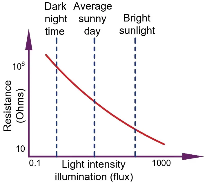
The resistance of LDR decreases when the light on the LDR is decreased, and when the LDR is kept in the dark, its resistance increases, and it is called the dark resistance.
When there is no light, the resistance is very high, in the Mega Ohm range. When light falls on it, the resistance decreases to Kilo Ohms.
Advantages and Disadvantages of Light-Dependent Resistors(LDRs)
The advantages of LDR are,
- They are cost-effective.
- Simple Design and Implementation
- Wide Range of Resistance Change
- Durability
- Low Power Consumption
- Versatile Applications
- High Sensitivity
The disadvantages of LDR are,
- Slow Response Time
- Non-Linear Response
- Temperature Sensitivity
- Limited Spectral Response
- Lower Precision
- Aging and Degradation
Difference between LDR and other Photo Detectors
When comparing light-dependent resistors (LDRs) to other photodetectors like photodiodes and phototransistors, it’s crucial to notice their fundamental differences in operation and structure.
1. Passive vs. Active Components
- LDRs: At their core, LDRs are passive devices. They do not include a PN junction, a characteristic that sets them apart from their photodetector counterparts. This absence of a PN junction means that LDRs do not actively produce current; instead, they merely change resistance in response to light exposure.
- Photodiodes and Phototransistors: In contrast, both photodiodes and phototransistors are active components. They incorporate a PN junction, which enables them to generate an electric current when exposed to light. This active response is a key differentiator that allows these devices to directly convert light into electrical signals.
2. Response Time
- LDRs: Typically have a slower response time due to their simple resistive nature. This makes them suitable for applications where rapid changes in light need not be detected.
- Photodiodes and Phototransistors: Possess faster response times, thanks to their semiconductor junctions. This makes them ideal for high-speed and precise light sensing applications.
3. Applications and Suitability
- LDRs: Best suited for tasks like light-sensing in street lamps or ambient light detection in displays, where gradual light changes are prevalent.
- Photodiodes and Phototransistors: Optimal for digital applications requiring quick light detection, such as in optical communications and high-speed counting.
In summary, while LDRs, photodiodes, and phototransistors all serve as photodetectors, they vary significantly in their functionality and application due to their fundamental operational differences.
LDR Circuit Diagram
The LDR circuit diagram is given below.
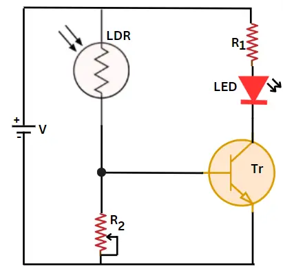
LDR is connected in the series with variable resistance R2. In the dark, the LDR resistance is very high, and it acts as an open circuit; therefore, the voltage across the variable resistor R2 is almost zero. The voltage across R2 is fed to the base and emitter junction of the transistor. In this condition, the transistor does not get enough voltage, and it remains in the off state, and the LED connected to the collector of the transistor does not glow.
When the light falls on LDR, the LDR resistance decreases, and current flows through the LDR and variable resistor R2. The voltage across R2 turns on the transistor, and the collector current flows through the LED and glows. You can use a relay instead of an LED to control the street lights or high-power equipment.
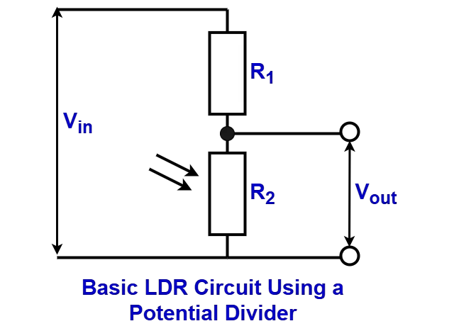
These LDR circuits can be based on bipolar transistors, FETs, operational amplifiers, and more. However, the foundation of most LDR circuits is a potential divider. This can then be used with various other circuits to process the voltage as needed.
A basic potential divider has two resistors in series. One end is typically connected to a fixed potential, and the other is connected to the ground.
The output voltage of the above potential divider can be determined using the formula below.
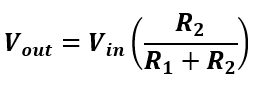
Note: This assumes that the potential divider circuit’s output is not affected by a load that could significantly alter the voltage. In most cases, a high-impedance load ensures the circuit operates as intended. If the load is not high-impedance, then the load and R2 should be treated as a parallel combination to determine the overall resistance of the lower part of the potential divider.
If the light-dependent resistor is R2, its resistance will change, causing the output voltage from the potential divider to change. This output voltage can then be connected to a transistor, FET, operational amplifier, or another suitable circuit. It can be used to amplify the difference or applied in various other circuits in different ways.
For example, if an LDR resistance varies between 100kΩ in low light and 1kΩ when illuminated, and the potential divider is powered with 20V, with R1 being 50kΩ, the output voltage will change. Assuming no load, the output voltage will range from 6.66V in low light to 0.392V in full light.
This voltage can easily be fed into a comparator or other suitable circuit. It can then be used to drive a logic line for further processing.
Applications of LDR
Because of their light sensitivity, light-dependent resistors (LDRs) have a wide range of applications in a variety of industries as listed below.
- Automatic street light control system
- Day-night switches for outdoor lighting
- Security system
- Solar-powered lighting system
- Light-sensitive Garden watering system
- Photographic light meters
- Light-sensitive doorbell activation
- Light-sensitive pet feeders
- Optical circuit design using the LDR
- Clock radios with LDR
- Simple smoke detector alarm by using the LDR
- Light-sensitive exterior vehicle lighting
- Used in infrared astronomy
- Automatic contrast and brightness control in television receivers
These applications demonstrate LDRs’ versatility and practicality in responding to changes in light intensity and being integrated into a variety of devices and systems for automatic and responsive functionality.
LDRs are very useful electronic components. They are used in various light-sensing applications and electronic circuit designs. Since their resistance changes over a wide range, LDRs are particularly useful. Because of this, many LDR circuit designs are available.
Light-dependent resistors (LDRs) or photoresistors are widely used. Although their performance is slow, they are still effective and low-cost. They can detect light and measure general light levels. As a result, they are used in low-light sensors for switching lights. They are also found in various sensors and many other applications.
Conclusion
The LDR stands for Light Dependent Resistor. It is also known as a light-controlled variable resistor, a photoresistor, or a photo-conducting cell. When exposed to light, its resistance changes, as the name implies. As a result, it is a light-sensitive electrical component.
It is made of semiconductor material, and its resistance reduces with increasing light intensity. When the intensity of light is reduced, its resistance increases. It operates on the photoconductivity principle.
When light strikes an LDR, the photons’ energy is absorbed by the semiconductor material. The absorbed energy by the semiconductor material allows the charge carriers to be released, increasing conductivity. There are two types of LDR that were discussed in detail. In the end, we studied the latency of LDR, technical specifications, and applications of LDR.