In digital electronics, the NOR Gate is a fundamental universal logic gate used to perform the logical NOR (NOT-OR) operation on binary inputs. It produces a high output only when all inputs are low and plays an important role in digital circuits and logic design applications.
In this article, we will discuss the definition, symbol, truth table, and equivalent circuit diagram of a logic NOR gate. So let’s get started with the basic definition of NOR Gate.
What is a NOR Gate?
In digital logic circuits, the NOR gate is a type of universal logic gate that combines the operation of two basic logic gates namely, OR gate and NOT gate. Therefore, it is also specified as a NOTed OR Gate.
The NOR gate produces a high output (1) only when all inputs are low (0). If any input is high (1), the output becomes low (0).
In simple terms, the NOR gate gives the inverted output of an OR gate.
It is considered a universal logic gate because it can perform all three basic logic operations: OR, AND, and NOT.
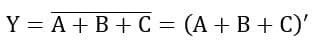
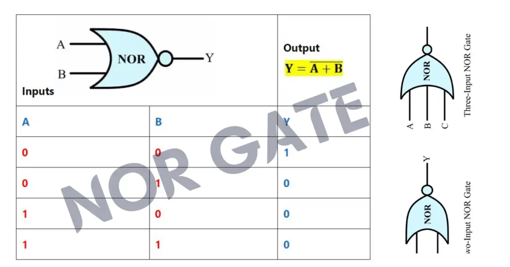
The Boolean expression of a NOR gate is Y = (A + B)’, where ‘+’ represents the logical OR operation, A and B are inputs, and Y is the output. The ( )’ denotes the logical NOT operation applied to the OR result. This expression can also be extended for multiple inputs in digital systems as Y = (A + B + C + …)’, where the output is 1 only when all inputs are 0.
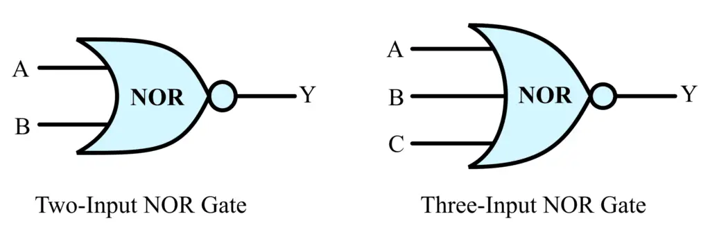
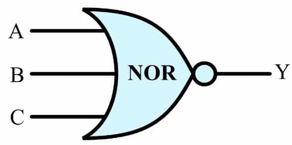
Symbol of NOR gate
The logic symbols of two-input and three-input NOR gates are represented in the following figure.
Logic Implementation of NOR Gate
A NOR gate can be formed by connecting an OR gate followed by a NOT gate, as shown in the figure below.
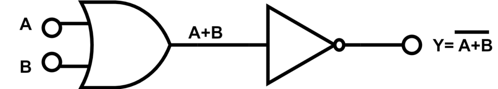
The OR gate first performs the logical OR operation on the input signals. Its output is then inverted by the NOT gate to produce the same output as a NOR gate.
Types of NOR Gate
NOR gates are classified based on the number of inputs as follows:
- 2-input NOR gate
- 3-input NOR gate
- Multi-input NOR gate
2-Input NOR Gate
The 2-input NOR gate is the most basic type of NOR gate. It has two input terminals and one output terminal. Since each input can have either 0 or 1, there are a total of 2² = 4 possible input combinations.
Logical Expression of 2-Input NOR Gate
The logic expression of a two-input NOR gate is given by the following equation:
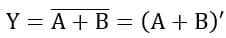
Where, Y is the output of the NOR gate, and A and B are the input variables of the NOR gate
2-Input NOR Gate Operation
The operation of a 2-input NOR gate for different input combinations is described as follows:
- When A = 0 and B = 0 → Y = 1
- When A = 0 and B = 1 → Y = 0
- When A = 1 and B = 0 → Y = 0
- When A = 1 and B = 1 → Y = 0
2-input NOR Gate Truth Table
The truth table is a table that represents the operation of a logic gate for different input combinations. The truth table of a 2-input NOR gate is given below.
Inputs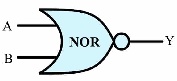 | Output | |
| A | B | Y |
| 0 | 0 | 1 |
| 0 | 1 | 0 |
| 1 | 0 | 0 |
| 1 | 1 | 0 |
3-Input NOR Gate
A 3-input NOR gate consists of three input variables and one output. It can also be formed by cascading multiple NOR gates to handle a larger number of inputs. For a 3-input NOR gate, there are a total of 23=8 possible input combinations.
Logic Expression of 3-Input NOR Gate
The Boolean expression is written using the logical OR operation followed by inversion, representing the NOR function.
For the three-input NOR gate, the logical expression is given by the following equation:
3-Input NOR Gate Operation
The operation of a three-input NOR gate is described below.
- When A = 0, B = 0, and C = 0 → Y = 1
- When A = 0, B = 0, and C = 1 → Y = 0
- When A = 0, B = 1, and C = 0 → Y = 0
- When A = 0, B = 1, and C = 1 → Y = 0
- When A = 1, B = 0, and C = 0 → Y = 0
- When A = 1, B = 0, and C = 1 → Y = 0
- When A = 1, B = 1, and C = 0 → Y = 0
- When A = 1, B = 1, and C = 1 → Y = 0
3-input Logic NOR Gate Truth Table
For the three-input NOR gate, the truth table is given below:
 Inputs | Output | ||
| A | B | C | Y |
| 0 | 0 | 0 | 1 |
| 0 | 0 | 1 | 0 |
| 0 | 1 | 0 | 0 |
| 0 | 1 | 1 | 0 |
| 1 | 0 | 0 | 0 |
| 1 | 0 | 1 | 0 |
| 1 | 1 | 0 | 0 |
| 1 | 1 | 1 | 0 |
Multi-input NOR gate
A NOR gate can be designed with any number of inputs, represented as n inputs. The output becomes high (1) only when all inputs are low (0). If even one input is high (1), the output turns low (0). For an n-input NOR gate, there are a total of 2ⁿ possible input combinations.
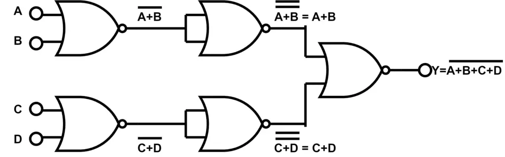
The 4-input NOR function shown in the figure below is implemented using five 2-input NOR gates. The number of gates required may vary depending on the implementation.
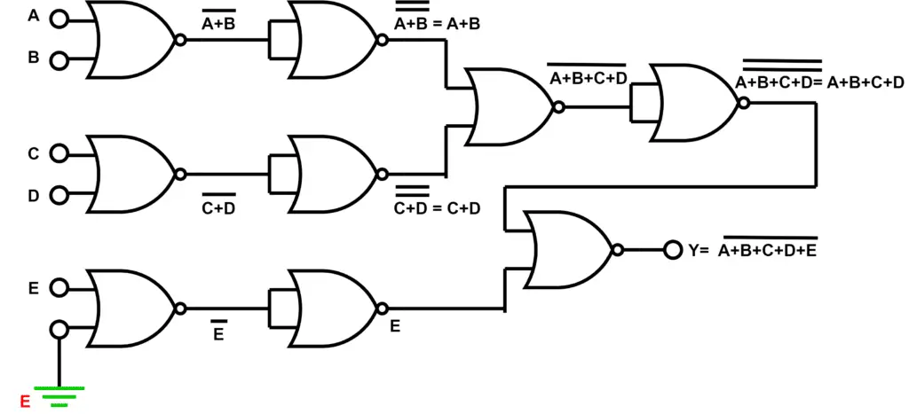
For the 5-input NOR function shown in the image below, nine 2-input NOR gates are used to implement the circuit. Since one input of a 2-input NOR gate remains unused, it is connected to logic LOW (ground) to ensure proper circuit operation.
The Logic NOR Gate function is also called the Pierce Function and it is denoted by a downwards arrow operator as A↓B.
Equivalent Circuit Diagram of NOR Gate (Switch and lamp circuit)
The equivalent circuit diagram or switching circuit diagram of a NOR gate is shown in the image below. It illustrates the working principle of a NOR gate using two switches connected in parallel.
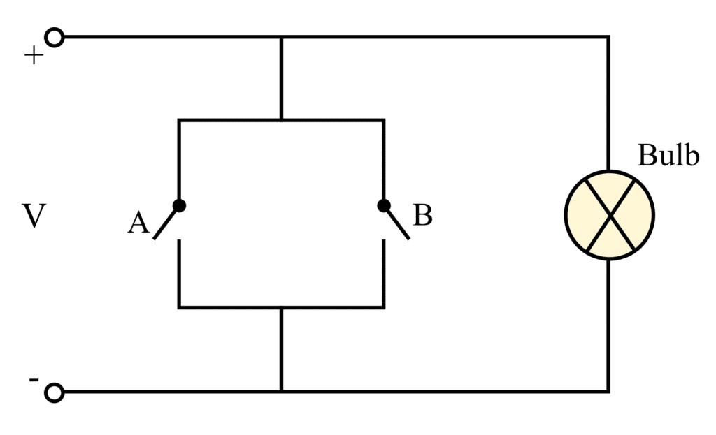
When both switches A and B remain open (logic 0), the circuit is complete and the bulb glows, indicating a HIGH (1) output. If either switch A or B, or both switches, are closed (logic 1), the current bypasses the bulb, causing it to remain OFF and producing a LOW (0) output.
Logic NOR Gate Implemenation using Transistors
Logic Nor Gate can be constructed using a transistor and resistor circuit. The circuit diagram of NOR gate using a combination of resistors and transistors is given below.
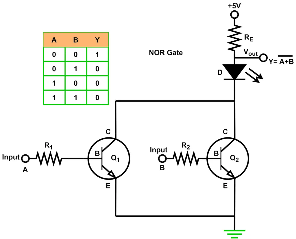
The operation of a transistor-based NOR gate is explained below:
- When A = 0 and B = 0: Both transistors Q1 and Q2 remain in the OFF state, so no collector current flows through either transistor. As a result, there is no voltage drop across resistor RE, and the output voltage (Vout) remains at 5 V (logic 1).
- When A = 0 and B = 1: Transistor Q2 turns ON, pulling the output voltage to 0 V (logic 0).
- When A = 1 and B = 0: Transistor Q1 turns ON, causing the output voltage to become 0 V (logic 0).
- When A = 1 and B = 1: Both Q1 and Q2 turn ON, pulling the output voltage to 0 V (logic 0).
NOR Gate Integrated Circuits
The following NOR gate integrated circuits (ICs) are commonly used in digital electronic circuits.
| TTL Logic NOR Gates | CMOS Logic NOR Gates |
| 74LS02 Quad 2-input | CD4001 Quad 2-input |
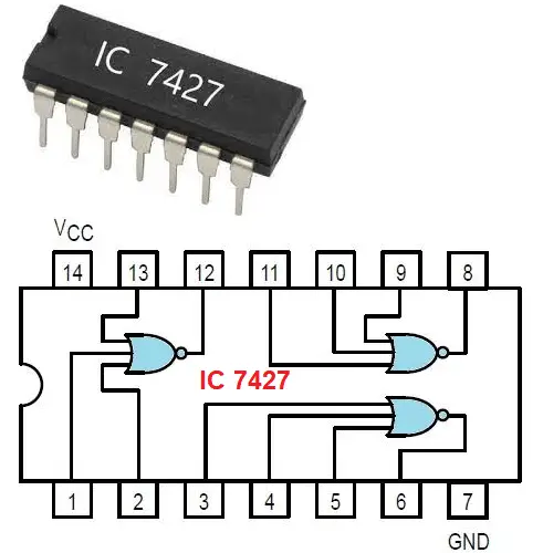
| 74LS27 Triple 3-input | CD4025 Triple 3-input |
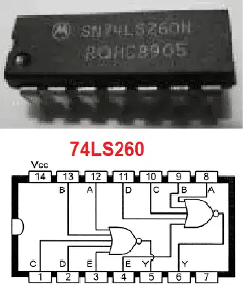
| 74LS260 Dual 5-input | CD4002 Dual 4-input |
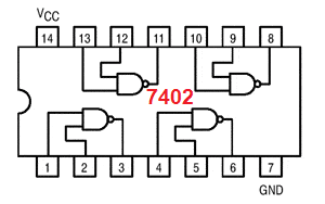
7402 Quad 2-input Logic NOR Gate
Pinout diagram of 7402 IC is:
74LS27 Triple 3-input
It contains three inputs NOR gates.
74LS260 Dual 5-input
It has five inputs NOR gates.
Applications of NOR Gate
The following are some common applications of NOR gates in digital electronics:
- Logic Gate Implementation: Since the NOR gate is a universal gate, it can be used to build other logic gates such as AND, OR, and NOT by connecting multiple NOR gates together.
- Inverter Circuits: A NOR gate can operate as a NOT gate by grounding one input and applying the signal to the other input.
- Decoder Circuits: NOR gates are widely used in decoders for memory addressing, data selection, and digital control systems.
- Arithmetic Circuits: They are used in digital arithmetic circuits, including adders and subtractors, to perform logical operations on binary data.
- Programmable Logic Devices (PLDs): NOR gates are commonly employed in programmable logic devices to implement customized digital logic functions.
Advantages of NOR Gate
The main advantages of a NOR gate are:
- Universal Gate: It can be used to implement all basic logic gates and any Boolean function.
- Simple Circuit Design: NOR gate circuits are easy to design, understand, and troubleshoot.
- Low Power Consumption: They generally consume less power in many digital electronic applications.
- Good Noise Immunity: NOR gates offer reliable operation even in the presence of electrical noise.
- Cost-Effective: Their simple construction makes them economical for use in digital circuits.
Disadvantages of NOR Gate
Despite its advantages, the NOR gate has some limitations:
- Higher Circuit Complexity: Implementing complex logic functions using only NOR gates may require additional gates.
- Propagation Delay: Cascading multiple NOR gates can increase the overall response time of the circuit.
- Not Always the Best Choice: For some digital circuits, other logic gates may provide a simpler and more efficient implementation.
- Additional Components: Complex logic designs built entirely with NOR gates often require more components, increasing circuit size and complexity.
Conclusion
NOR gates are fundamental building blocks of digital electronics and are widely used in logic circuit design. As a universal logic gate, a NOR gate can be used to implement all basic logic functions, including AND, OR, and NOT. It produces a HIGH (1) output only when all its inputs are LOW (0), making it suitable for a wide range of digital applications. Understanding the NOR gate’s symbol, Boolean expression, truth table, working principle, and implementation is essential for designing and analyzing digital electronic circui
Read Next:
- Logic Gates: Types, Working, Symbols, Truth Tables, Boolean Expressions
- XNOR Gate: Symbol and Truth Table
- What is a NOT Gate? Logic Symbol and Truth Table
- Exclusive-OR Gate with EX-OR Gate Truth Table
- Universal Logic Gate: NAND Gate and NOR Gate as Universal Gate
- Logic NAND Gate- Symbol, Truth Table, Circuit Diagram, Working
- Logic AND Gate: Symbol, Truth Table, Working, Circuit Diagram
- Logic OR Gate: Symbol, Truth Table, Working, Types & IC Numbers