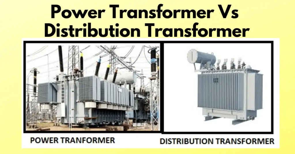
The primary difference between a power transformer and a distribution transformer is their application and operating voltage. Power transformers are used in high-voltage transmission systems, typically at 33 kV to 400 kV, and usually have ratings above 200 MVA. In contrast, distribution transformers operate in lower-voltage distribution networks, such as 11 kV, 6.6 kV, 3.3 kV, 440 V, and 230 V, to supply electricity to consumers, and are generally rated below 200 MVA.
Although both transformers are used to step up or step down AC voltage in power systems, they differ significantly in their design, operating conditions, efficiency, voltage regulation, loading characteristics, and applications.
In this article, we will discuss the difference between power transformers and distribution transformers in detail.
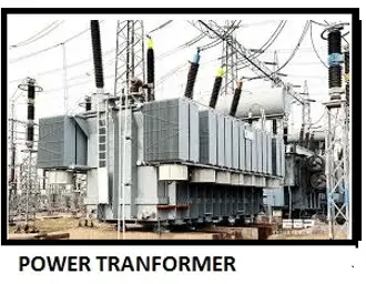
What is a Power Transformer?
A power transformer is an electrical transformer used in high-voltage transmission systems to increase or decrease voltage levels. At the generating station, it steps up the generated voltage for long-distance transmission, which helps minimize transmission line losses. At transmission substations, it steps down the voltage to the required level for further transmission or distribution.
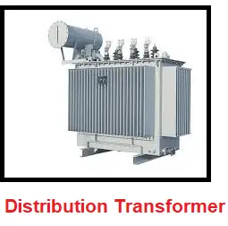
What is a Distribution Transformer?
A distribution transformer is an electrical transformer used in distribution networks to reduce the voltage to a level suitable for residential, commercial, and industrial consumers. It is installed near the load center and supplies electrical power directly to end users.
A distribution transformer functions as a step-down transformer, converting the primary distribution voltage to the required utilization voltage. Unlike a power transformer, it is designed to operate efficiently under varying load conditions throughout the day, as consumer demand continuously changes.
Power Transformer vs. Distribution Transformer: Key Differences
The following sections explain the key differences between power transformers and distribution transformers based on their design, operating characteristics, efficiency, insulation, applications, and other technical parameters.
Size of Transformer
Power transformers are designed for high-voltage transmission systems, typically operating at high voltage 33 kV to 400 kV with ratings above 200 MVA. As a result, they are physically larger, heavier, and require more installation space than distribution transformers. In contrast, distribution transformers generally operate at 33 kV and below with ratings below 200 MVA, making them smaller, lighter, and easier to install near load centers.
Insulation level
Power transformers operate at high transmission voltages, typically above 33 kV, and therefore require a higher insulation level than distribution transformers. Since they are generally installed outdoors, their insulation is designed to withstand switching and lightning impulses. Distribution transformers operate at 33 kV and below, so their insulation requirements are comparatively lower.
Iron Losses, Copper Losses & Efficiency
Power transformers are designed to operate at or near full load for most of their service life. Under these conditions, copper (I²R) losses become more dominant than iron losses. Therefore, they are designed with a higher flux density (typically 1.7–1.8 T), which reduces the number of winding turns and consequently lowers copper losses. Although this increases core (iron) losses, the trade-off improves efficiency during full-load operation.
To maximize utilization of the magnetic core material, power transformers are designed to operate very close to the knee point of the B-H magnetization curve. This enables a smaller and lighter core for a given power rating, reducing the overall size, weight, and cost of the transformer.
In contrast, distribution transformers operate under continuously varying loads depending on consumer demand and remain energized for 24 hours. As iron (core) losses occur continuously whenever the transformer is energized, they become more significant than copper losses. Hence, distribution transformers are designed with a lower flux density to reduce iron losses and improve overall performance under light-load conditions.
Maximum Efficiency
From an efficiency perspective, power transformers are evaluated based on full-load efficiency, as they typically operate near rated load. Distribution transformers, however, are assessed based on all-day efficiency, since their load varies throughout the day. Their maximum efficiency usually occurs at around 60–70% of full load, balancing iron and copper losses for optimal daily performance.
Load Fluctuations and Placement
Power transformers are generally installed in generating stations and transmission substations, where they are not directly connected to end consumers. As a result, they experience minimal load fluctuations and are designed to operate continuously at or near full load under relatively stable operating conditions.
In contrast, distribution transformers are installed closer to end users, such as residential, commercial, and industrial areas. Since they directly supply electricity to consumers, they are subjected to highly variable and unpredictable load patterns throughout the day. Their thermal design is therefore based on handling localized load clusters rather than continuous full-load operation, ensuring reliable performance under fluctuating demand conditions.
Summary Table: Power Transformer vs Distribution Transformer
The following table presents comparison between power transformers and distribution transformers based on key parameters such as design, operating conditions, efficiency, and applications in the electrical power system.
| Point of Comparison | Distribution Transformer | Power Transformer |
| Definition | Steps down high voltage to low voltage for end users. | Steps up and steps down voltage in transmission systems. |
| Purpose | Final voltage reduction for consumer supply. | Bulk power transfer over long distances. |
| Location | Near load centers / consumers. | Generating stations and transmission substations. |
| Function | Mainly step-down operation. | Step-up and step-down both. |
| Power rating | Less than 200 MVA. | More than 200 MVA. |
| Voltage rating | 11 kV, 6.6 kV, 3.3 kV, 440 V, 230 V, etc. | 33 kV, 66 kV, 132 kV, 220 kV, 400 kV and above. |
| Winding configuration | Primary delta, secondary star (neutral available). | Delta-delta, star-delta, or delta-star. |
| Number of windings | One primary and one secondary. | One primary and one secondary. |
| Size | Smaller and compact. | Large and heavy construction. |
| Operating period | Continuous operation with varying load. | Operates near full load for long periods. |
| Operation under light load | Frequently operates under light load. | Not economical at light load. |
| Load fluctuations | High load variation. | Low load variation. |
| Flux density | Lower flux density to reduce iron losses. | Higher flux density to reduce copper losses. |
| Iron losses | Lower. | Higher. |
| Copper losses | Higher. | Lower. |
| Maximum efficiency | At 60–70% of full load (all-day efficiency). | At or near full load. |
| Leakage reactance | Low (good regulation). | High (limits fault current). |
| Voltage regulation | Good regulation required. | Less critical. |
| Applications | Local distribution to consumers. | Transmission and generation network. |
Conclusion
Power transformers and distribution transformers differ significantly in their design, operating conditions, efficiency, and applications in the electrical power system.
Power transformers are primarily used for efficient bulk power transfer in transmission networks, while distribution transformers are designed to deliver electricity safely and efficiently to end users under varying load conditions. Therefore, the selection of a transformer depends on its specific role in the power system, ensuring reliable, economical, and efficient power delivery from generation to consumption.
Read Next: