Nominal T model of a medium transmission line has two components- series impedance and shunt admittance. In this post, we shall discuss the nominal T model of a medium transmission line. In a nominal T model of a transmission line;
- The series impedance is divided into two equal parts.
- The shunt admittance is concentrated at the center of the line.
Nominal-T Representation:
The nominal T model of a medium transmission line is as shown below.
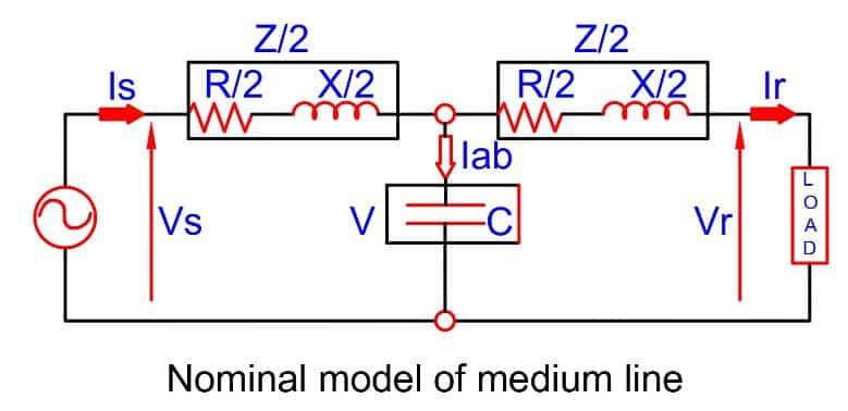
Where,
Series impedance of the line Z = R + jX
Shunt admittance of the line Y = jwc
Receiving end voltage = Vr
Receiving end current = Ir
Current in the capacitor = Iab
Sending end voltage = Vs
Sending end current = Is
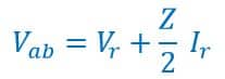
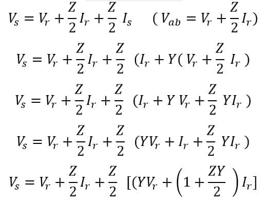
By KCL and KVL rules, We can calculate the sending end voltage and current. The voltage across the capacitors is ;
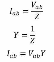
The current flowing through capacitor is
From above equations, we can calculate the sending end voltage and current.
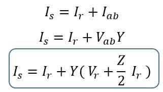
The sending end voltage is ;
Sending end voltage and current is as written in matrix form;
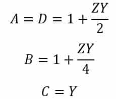
The A,B,C and D constant of medium transmission line is.
| Read More on Electricalvolt |
| Classification of Transmission Line |
The phasor diagram of the nominal T-circuit for a lagging power factor is as shown below.
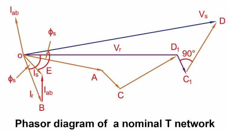
Abbreviation in Phasor Diagram
OA = Vr – receiving end voltage to neutral, as reference voltage
OB = Ir – load current lagging Vr by an angle ∅. Where, cos∅ is the power factor of the load.
AC = IrR/2 – Voltage drop in the reactance of the right-hand half of the line. It is 90 degree to OB, i.e., Ir.
OD1 = Vab – voltage at the midpoint of the line across the capacitance C.
BE = Iab – current in the capacitor. It leads the voltage Vab by 90.
OE = Is -sending-end current, the phasor sum of load current and capacitor current.
D1C1 = IsR/2 – voltage drop in the resistance on the left-hand side of the lines.It is perpendicular to Is.
C1D = Is X/2 – voltage drop in the reactance in the left half of the line. It is perpendicular to Is
OD = Vs – sending end voltage. It is the phasor sum of the of Vab and the impedance voltage drop in the left-hand half of the line.
∅s – phase angle at the sending end. cos∅s is the power factor at the sending end of the line.
Read Next: