What is a DC Machine?
A Direct Current (DC) machine operates using direct current (DC) to either:
- Convert electrical energy into mechanical energy (when functioning as a motor), or
- Convert mechanical energy into electrical energy (when functioning as a generator).
These machines play a crucial role in various industrial, commercial, and household applications.
Electric rotating machines are used to convert electrical energy into mechanical energy or mechanical energy into electrical energy. DC motor converts electrical energy into mechanical energy, and the DC generator converts mechanical energy into electrical energy.
Why Losses Occur in DC Machines?
During energy conversion, the input energy in one form can not be fully converted into output energy in another form. The difference in the output energy and input energy is called the losses.
In reality, no machine is 100 % efficient, and some losses always occur during the energy conversion. The losses cause an increase in the machine’s temperature, which reduces its efficiency. In a DC machine, the energy loss takes place in the form of heat energy in the armature and field of the DC machine. There are five types of losses: copper loss, brush loss, iron loss, stray loss, and mechanical loss, which occur in a DC machine.
Importance of DC Machines in Different Industries
- In the manufacturing industry, powered machine tools provide precise movements.
- Drive conveyors to facilitate material movement on assembly lines.
- In the automotive industry, high torque at low speeds powers electric vehicles.
- Start traditional internal combustion engine vehicles.
- The renewable energy sector transforms mechanical energy from wind turbines into electricity.
- Harness water’s kinetic energy in hydroelectric plants to generate electricity.
- In aerospace and aviation, actuators and control systems ensure precise movements.
- Serve as auxiliary power units for airplanes.
- Home Appliances: Power blenders, mixers, and food processors.
- Run HVAC fans and blowers to maintain household comfort.
- Generators and utilities serve as backup power sources for emergency systems.
- Provide backup power to ensure uninterrupted communication.
- Power robotic arms and automated machinery in manufacturing processes.
- Robotic movements require precise control of speed and torque.
Significance of DC Machines
Reliability: DC motors are known for their reliability and durability.
Control: Many applications demand precise control of speed and torque.
Adaptability: DC motors can function in various environments and with different power sources.
Overview of DC Machine Losses
Power loss occurs during the conversion of input power to output power, leading to a decrease in machine efficiency.
Output Power = Input Power – Losses
The efficiency ratio is determined by dividing the output power by the input power. Designing a high-efficiency DC machine requires a thorough understanding of the losses that occur within the machine.
The losses are the difference between the input power and the output power.
No machine is 100% efficient, as some energy is always lost during the conversion process. The losses generate heat, raising the equipment’s temperature and reducing its efficiency. In a direct current (DC) machine, heat energy is lost. These losses occur in both the armature and the field of the DC machine.
Importance for Recognizing Losses in the DC Machines
Understanding DC machine losses is crucial for several reasons:
- Improved Efficiency: Identifying and reducing losses leads to enhanced machine performance.
- Cost Reduction: Optimizing designs and materials helps lower energy-related operational costs.
- Loss Minimization: Reducing losses boosts output and increases the reliability of the application.
- Resource Conservation: Supports energy savings and sustainability efforts.
- Maintenance Planning: Recognizing specific losses helps predict and monitor equipment health.
- Regulatory Compliance: Understanding and managing losses ensures compliance with energy efficiency standards.
- Technological Advancements: Research on losses drives innovation in DC machine design and operation.
- Educational Significance: Essential for electrical engineering education, preparing future engineers.
- Problem-Solving and Optimization: Addressing inefficiencies and fine-tuning machines for better performance.
What is the formula for Electrical Loss?
P (Loss) = I² R
Where,
P – Power
I – Current and
R – Resistance
This illustrates a key principle in electrical theory: by increasing the voltage, as expressed by the formula V=IR, losses are significantly reduced. When the voltage is raised, the current (I) required to transmit the same power is reduced, which directly lowers the resistive losses.
Different Types of Losses in DC Machines
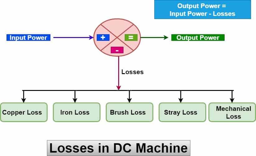
Losses in a DC machine are categorized into five types, as explained in detail below.
- Electrical (or) Copper losses
- Magnetic Losses (or) Core Losses (or) Iron Losses
- Brush Losses
- Mechanical Losses
- Stray Losses
We shall discuss the types of losses in a DC machine for better understanding.
Electrical (or) Copper losses in DC Machine
Electrical or copper losses, also known as winding losses, occur due to the resistance in the windings. The copper loss is caused by the ohmic resistance offered by the winding of the DC machine. When the current flows through the winding, heat loss takes place. The heat loss is proportional to the square of the current and the resistance of the winding.
The copper loss in the winding is I2R. Where I is the current flowing through the winding, and R is the resistance of the winding. Copper loss is also known as variable loss because it depends on the percentage loading of the machine. The loss increases with the increase of loading on the machine.
The DC machine has two types of winding- field and armature winding- and losses occur in both windings. The supply is fed to the armature through the carbon brushes, and losses also occur due to ohmic voltage drops across the carbon brush.
1). Copper Loss in Armature Winding
The armature of the DC machine has very low resistance. The copper loss in the armature winding is,
Armature copper loss = Ia2Ra
Where
Ia is the armature current
Ra is the armature winding resistance.
The maximum copper loss occurs in the armature winding because the load current flows through it. The copper loss in the armature is about 25 to 30 % of the full load loss.
2). Copper Loss in Field Winding
DC supply is fed to the field winding for the production of the flux in the DC machine. The resistance of the field winding is much higher than the resistance of the armature winding. For this reason, there is significant copper loss in the field winding, even at the low field current. The copper loss in the field winding is expressed as;
Field Winding Copper Loss = If2Rf
Where,
If is the field current and.
Rf is the field winding resistance.
The field winding copper loss is about 20-25 % of the full load loss of the DC machine. The copper loss in the field winding is practically constant because the field current and the field resistance remain almost constant in the DC machine.
Shunt Machine: In a shunt machine, the copper loss in the shunt field is given by:
Copper losses (Shunt) = I2shRsh
Where,
Ish-Shunt Field Current and
Rsh-Resistance of Shunt Field Windings.
Series Machine: In a series machine, the copper loss in the series windings is given by,
Copper losses (Series) = I2seRse
Where,
Ise– Series Field Current and
Rse– Resistance of Series Field Windings.
Compound Machine: A compound machine consists of both shunt and series field windings, where copper losses occur in both windings. These losses contribute to more than 20% of the total load losses.
Interpole Windings: Copper losses in interpole windings are represented as the power dissipated due to the resistance of the interpole coils and the current flowing through them. These losses contribute to the overall energy dissipation in the machine, affecting efficiency and performance. The copper loss in the interpole winding is given by,
Copper losses (Interpole Windings) = Ia2Ri
Where,
Ri-Resistance of the Interpole Windings.
Compensating Windings: Copper loss in compensating windings, if present, is the power dissipated due to the resistance of these windings and the current flowing through them. Compensating windings are used in larger DC machines to counteract armature reaction and improve commutation. The losses in these windings contribute to the overall energy dissipation in the machine, affecting efficiency.
Copper loss in compensating windings is given by,
Copper losses (Compensating Windings) = Ia2Rc
Where,
Rc– Resistance of Compensating Windings
Standards for Electrical (Copper) Losses in DC Machines
- IEC 60034-1: Specifies standard methods for testing efficiency and losses in rotating electrical machines, including DC machines.
- IEEE 112: Defines test procedures for evaluating the performance of DC machines.
Magnetic Losses (or) Iron Losses (or) Core Losses in DC Machine
The armature winding of the DC machine is wound around the magnetic core. The flux generated by the field coil links to the armature conductors through a magnetic core. The losses occur in the armature core, therefore it is called core loss. The iron loss is almost constant; therefore, the iron loss or core loss is also called constant loss. The total core loss is about 20-25 % of the full load losses.
The losses occur in the armature core
- Hysteresis Losses
- Eddy current losses
are the two types of iron (or) core losses.
1). Hysteresis Loss in DC Machine
Hysteresis loss refers to the core loss occurring in the armature core of a DC machine due to the reversal of the magnetic field as it passes under successive magnetic poles with different polarities.
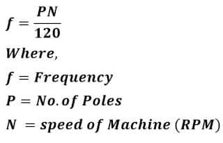
The armature of the DC machine rotates in a magnetic field, and in one complete rotation, the magnetic field reversal happens. The part of the armature remains under the S-pole for half a revolution, and after completing half the revolution under the S-pole, the part of the armature goes under the P-pole for the remaining half cycle. Thus, in one complete cycle, the magnetic field reversal happens in the armature core. The frequency of the magnetic reversal can be found by the following mathematical expression.
Due to constant magnetic reversal in the armature, some energy consumed during magnetic reversal is called hysteresis loss. The hysteresis loss depends on the quality and volume of the core material.
The hysteresis loss in the DC machine can be calculated using the following Steinmetz formula.
Hysteresis Loss (Ph) = η B1.6max f V
Where,
Ph = hysteresis loss (Watt)
Bm = Maximum flux density (Wb/m2)
n =Steinmetz exponent, ranges from 1.5 to 2.5, depending on the material
f = frequency of magnetic reversals per second (Hz)
V = volume of magnetic material (m3)
The hysteresis loss in DC machines can be significantly reduced by using materials like silicon steel for the armature core, as they have a low Steinmetz hysteresis coefficient.
2). Eddy Current Loss
The armature of the DC machine is wound on the magnetic core, and the magnetic core rotates in the magnetic field. According to Faraday’s law of electromagnetic induction, an EMF is induced in the core.
The magnetic core has a certain resistance, and the induced EMF causes current to circulate within the piece of the magnetic core. The circulation current, called eddy current, causes the wastage of electrical energy. The loss caused by the eddy current is called the eddy current loss in a DC machine. The eddy current loss can be minimized by the use of a laminated core.
The eddy current loss can be dtermined by the following formula.
Eddy Current Loss (Pe) = ke B2max f2 t2 V
Where,
Pe= Eddy current loss(watt)
B= Maximum flux density Wb/m2
f= frequency in Hz
t= thickness of lamination (m)
V= Volume of the material (m3)
K= Eddy Current Constant
The eddy current loss equation clearly shows that eddy current loss depends on the square of the lamination thickness.
Therefore, to minimize this loss, the armature core is made of thin laminations, each separated by a thin layer of varnish.
Brush Losses in DC Machine
The armature is a rotating part of the DC machine, and brushes are used to provide a DC supply to the rotating part of the DC machine. Ideally, the contact resistance between the brush contacting area and the commutator surface must be zero. However, in reality, it is impossible to achieve zero contact resistance.
The voltage drop takes place across the carbon brushes. The brush power drop is determined by the voltage drop across the brush and the armature current.
The losses that take place between the carbon brushes and the commutator are known as brush losses.
Power loss occurs at the brush contact point, which is influenced by the armature current (Ia) and the voltage drop across the brush contact. It is given by the following equation:
Power Drop in Brush = PBD = VBD Ia
Where,
PBD = Power drop in Brush
VBD = Voltage Drop in Brush
Ia = Armature Current
The voltage drop across a set of brushes remains approximately constant over a wide range of armature currents.
If the brush voltage drop is not given, it is generally assumed that 2-volt drops across the carbon brush, and the power drop in the brush is 2Ia. The brush power loss can not be calculated separately, but it is included in the armature copper loss of the DC machine.
Mechanical Loss in DC Machine
Mechanical losses arise due to the mechanical effects within the machine.
These losses are proportional to machine speed but remain nearly constant at a fixed speed.
Mechanical losses are categorized into:
- Friction Loss
- Windage Loss
1). Friction Loss
In a DC machine, the field is a stationary part, and the armature is a rotating part. The armature rotates on the bearings. The energy loss in the form of heat occurs due to friction between the inner cage and outer cage of the bearing.
2). Windage Loss
The other mechanical loss is the windage loss. The air surrounding the shaft offers resistance, and when the DC machine rotates, the loss caused by air resistance is called windage loss. The DC machine draws extra power from the source to overcome the air resistance, and the extra energy is equal to the windage loss of the DC machine. The windage loss increases with an increase in the speed of the rotating machine.
These losses account for approximately 10% to 20% of the total full-load losses.
Standards for Mechanical Losses in DC Machines
- IEC 60034-2-1: Covers mechanical vibration in rotating electrical machinery.
- IEEE 115: Specifies requirements for the mechanical components of electrical machines.
Stray Losses in DC Machine
Stray losses are miscellaneous losses that are difficult to determine. The various reasons for the stray losses in DC machines are short circuit current undergoing commutation, distortion of flux, etc. The stray losses in the DC machine are about 1 % of the total losses.
These losses primarily result from inaccuracies in the machine’s design and modeling.
Note: Iron (or core) losses and mechanical losses are collectively known as stray losses.
Standards for Stray Losses in DC Machines
- IEEE 62: Focuses on stray load losses in electrical machinery.
Category of Losses in DC Machine
The losses in DC machines can be categorized into two types:
- Constant Losses
- Variable Losses
The total losses in a DC machine are given by:
Total Losses = Constant Losses + Variable Losses
1). Constant Losses
Constant losses in a DC machine are the losses that remain unchanged regardless of the load. The constant losses in a DC machine include:
- Iron losses,
- Shunt field copper losses, and
- Mechanical losses
2). Variable Losses
Variable losses in a DC machine are the losses that change with the load. These include:
- Copper Losses (Armature and Field Winding Losses)
- Brush Contact Losses (Dependent on Load Current)
Experimental Methods to Determine DC Machine Losses
A. Open Circuit and Short Circuit Tests
- Open circuit test measures core and mechanical losses.
- Short circuit test determine copper losses.
B. Swinburne’s Test (No-Load Test)
- Conducted under no-load conditions.
- This test estimates efficiency at different loads without actually loading the machine.
C. Hopkinson’s Test (Back-to-Back Test)
- Two identical DC machines are tested together.
- Provides accurate loss measurement under full-load conditions.
Impact of Losses on DC Machine Performance
- Effect on Heating and Temperature Rise
- Higher losses lead to excessive heating, which degrades insulation.
- Overheating can reduce machine lifespan and efficiency.
- Influence on Machine Lifespan
- Increased losses accelerate wear and tear.
- Proper loss management extends operational life.
How can DC Machine Losses be minimized?
- Reducing Copper Losses
- Use conductors with lower resistance (e.g., high-purity copper).
- Optimize winding design to reduce resistance.
- Minimizing Iron (Core) Losses
- Use high-grade silicon steel with low hysteresis loss.
- Reduce the lamination thickness to minimize eddy current losses.
- Lowering Mechanical Losses
- Use high-quality bearings to reduce friction.
- Improve ventilation to minimize windage losses.
- Reducing Brush Losses
- Use high-quality carbon brushes with low contact resistance.
- Ensure proper brush maintenance and alignment.
- Optimizing Machine Design
- Improve machine cooling to reduce overheating losses.
- Use efficient magnetic circuit design to minimize stray losses.
Read Next: