A transformer is an essential electrical device that changes the voltage level of alternating current (AC) without altering its frequency. The working principle of a transformer is based on electromagnetic induction, enabling efficient power transfer between circuits.
What is Transformer?
A transformer is an electrical device that transfers energy between two or more circuits through electromagnetic induction. It changes the voltage level of AC power without changing its frequency.
Read detailed aartcile on: What is a Transformer? Definition & Meaning
Basic Principle of Transformer
The transformer works on Faraday’s law of electromagnetic induction, which states that a changing magnetic flux induces an electromotive force (EMF) in a coil.
- When AC voltage is applied to the primary winding, it produces a time-varying magnetic flux in the core.
- This flux links both primary and secondary windings.
- The induced EMF in each winding depends on:
- The number of turns in the winding
- The rate at which the magnetic flux changes
Working Principle of Transformer
The working principle of a transformer can be explained in three stages:
- Flux Creation in the Core – AC voltage applied to the primary winding causes current flow, producing an alternating magnetic flux in the laminated magnetic core.
- Flux Linkage – The core provides a low-reluctance path, ensuring maximum flux linkage to both primary and secondary windings.
- Voltage Induction in the Secondary – The linked magnetic flux induces an alternating voltage in the secondary winding. The voltage level depends on the turns ratio.
Transformer Theory: Basics and Principle of Operation
The magnitude of the induced electromotive force (EMF) in a coil depends on two main factors:
- The rate of change of magnetic flux
- The number of turns in the coil
According to Lenz’s Law, the induced EMF always acts in a direction that opposes the change causing it — in other words, it resists the applied voltage.
The induced EMF in a coil can be mathematically expressed as:
e = – N dФ/dt
where:
- e = induced EMF
- N = number of turns in the coil
- Φ = magnetic flux
Why Voltage is Stepped Up or Down in Transformers
In AC power systems, voltage is stepped up for long-distance transmission to minimize I²R losses and improve efficiency.
Higher voltage means lower current for the same power, which reduces heat loss in lines.
At the receiving end, the voltage is stepped down for safe use in homes and industries.
Read detailed article on: Why is a step up transformer used to transmit electrical energy?
EMF Equation of Transformer
The voltage induced in the primary and ssecondary winding of transformer,
Ep = 4.44Np fФm
Es = 4.44Ns fФm
Where,
Ep = Induced EMF in the primary winding
ES = Induced EMF in the secondary winding
Np = number of turns in the primary winding
Ns = number of turns in the secondary winding
f = Frequency
Фm = Flux in the core
Read detailed artcicle on: EMF Equation of Transformer and its Derivation
Turns Ratio & Voltage Transformation Ratio of Transformer
The EMF equation of the transformer is given below.
Ep = 4.44Np fФm ——-(1)
Es = 4.44Ns fФm ———(2)
Dividing equation (2) By (1) we get,
Es/Ep = Ns/ Np ———(3)
Voltages Es and Ep are almost equal to the primary and secondary terminal voltage if we ignore the winding resistance and the leakage reactance.
Es= Vs and Ep= Vp
Vs/Vp = Ns/ Np = K —-(4)
Where,
K is the voltage transformation ratio.
The input power of the transformer is almost equal to the output power.
Vs x Is = Vp x Ip
Vs/Vp = Ip/Is ———(5)
From equations (4) and (5) we get
Vs/Vp = Ns/Np = Ip/Is = K
The turns ratio is the ratio of primary turns to secondary turns.
Turns ratio = Np/Ns= 1/K
A transformer can be used to either increase or decrease voltage levels. When it increases the voltage from the primary side to the secondary side, it is called a step-up transformer. When it reduces the voltage from the primary to the secondary, it is called a step-down transformer.
In a step-down transformer, the number of turns in the primary is more than in the secondary.

In a step-up transformer, the number of turns in the primary winding (Np) is less than the number of turns in the secondary winding (Ns). This higher turns ratio on the secondary side increases the output voltage compared to the input voltage.

Read detailed article on: Turn Ratio of Transformer- Definition, Formula, Solved Problems
Transformer Core Flux Limits and Magnetic Saturation
The transformer core is designed to carry magnetic flux only up to its maximum rated capacity. For example, a CRGO (Cold Rolled Grain Oriented) steel core can safely handle flux densities up to about 1.9 Tesla.
If the flux density exceeds this limit, the core becomes magnetically saturated. This leads to:
- Distorted output voltage waveform
- Increased losses and reduced efficiency
Flux density is mainly affected by the ratio of voltage to frequency (V/f). If you increase voltage without increasing frequency, or lower frequency without lowering voltage, flux density rises and may push the core into saturation.
Read detailed article on: Transformer Over Fluxing Protection
Losses in Transformer
A transformer consists of primary and secondary windings wound on a common magnetic core. When an alternating voltage is applied to the primary winding, the transformer draws a small magnetizing current to establish magnetic flux in the core.
This alternating flux links both the primary and secondary windings, enabling voltage transformation.
In an ideal transformer, all the flux produced in the primary perfectly links to the secondary without leakage. In practice, however, some flux is lost — known as leakage flux.
To improve efficiency, transformer cores are made from Cold Rolled Grain Oriented (CRGO) steel, which offers high magnetic permeability, better flux linkage, and lower hysteresis losses.
Another core-related loss is eddy current loss, caused when the changing flux induces circulating currents within the core material. This not only wastes energy but also produces unwanted heating. To minimize this loss, the transformer’s magnetic core is laminated, increasing its resistance to these currents.
When the primary winding is supplied with sinusoidal (AC) voltage, the alternating current creates an alternating flux in the core. This flux links both the primary and secondary windings, inducing EMF in each.
The magnitude of EMF induced in the primary and secondary can be calculated using the transformer EMF equation.
Read detailed article on: Types of Losses in a Transformer
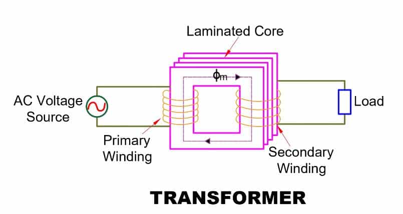
Main Parts of a Transformer
The transformer has three main parts.
- Primary Winding
- Magnetic Core
- Secondary Winding
Primary Winding
The primary winding is connected to an external power source and receives electrical energy from it. When supplied with alternating voltage, the primary winding produces an alternating magnetic flux in the transformer’s core.
Magnetic Core
The magnetic core offers a low-reluctance path for the magnetic flux. This flux links both the primary and secondary windings, inducing voltage in each according to the principle of electromagnetic induction.
Read detailed article on: What is Transformer Core? Construction, Working & Losses
Secondary Winding
The secondary winding is wound on the same magnetic core as the primary. The magnetic flux produced by the primary winding links to the secondary, inducing a voltage in it through electromagnetic induction.
Conclusion
Understanding the working principle of transformer helps in grasping how it efficiently changes voltage levels in AC power systems. By applying electromagnetic induction, transformers ensure minimal transmission losses, deliver safe voltage levels for various applications, and play a vital role in power generation, transmission, and distribution networks.
Related Articles:
You may also include all the necessary test procedures carried on transformer