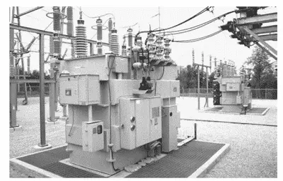
Transformers, even when not supplying any load, consume power—this is known as no-load loss or core loss. These losses occur as soon as the transformer is energized and remain constant regardless of the load connected. No-load losses primarily stem from the magnetizing current flowing in the transformer’s core and are influenced by the properties of the core material and supply voltage.
In this article, we’ll break down the concept of no-load losses, explain the formula for calculating core loss, and explore the two major components: hysteresis loss and eddy current loss. Understanding these losses is vital for improving transformer efficiency, reducing operating costs, and making informed choices in transformer design and selection.
What are No-Load Losses of Transformers?
No load losses (also known as core loss or iron loss in transformer) occur when the transformer is energized at the rated voltage and frequency, keeping its secondary open circuit. Transformer no-load losses occur because of the magnetic field.
These transformer excitation losses occur due to the alternating magnetic field in the core even when no load is connected.
Transformer no-load losses, also known as iron losses in transformer, are combined losses caused by eddy current loss in transformer, hysteresis loss in transformer, stray eddy current loss, and dielectric loss.
The maximum losses when the transformer is under no load occur in the core. Therefore, the No-Load losses of the transformer are also called iron loss or excitation loss.
Transformer no-load losses are constant from no load to full load; therefore, no-load losses are also called constant losses.
A transformer is a static device, and there are no moving parts in the transformer. Therefore, the friction and windage losses in the transformer are nil.
The transformer steps up or steps down the voltage, keeping the frequency unaltered. Transformer load losses and no load losses occur because of the current flowing in the winding and magnetic field in the core.
For an ideal transformer, the input power is equal to the output power, however, in reality, this is not true. The output power of the transformer is always less than the input power.
The energy can neither be created nor it can be destroyed; the same principle is applicable to the energy balancing of the transformer as well.
The power drawn at the primary is equal to the losses in the transformer plus the power delivered at the secondary side of the transformer.
Types of Losses in a Transformer
The losses in the transformer can be broadly categorized into two categories:
- Iron losses or core losses, dielectric loss, and stray eddy current loss
- Copper loss and stray losses
Types of No-Load Losses of Transformer
The voltage applied at the primary winding produces a magnetic field in the core. The flux produced due to the primary current passes through the core, gets linked to the secondary winding of the transformer, and induces a voltage in the secondary of the transformer.
In this induction process, when the transformer is at no load, it suffers from core losses, also called no load losses in transformer, which include hysteresis and eddy current effects.
These losses are constant, and therefore, the no-load losses are also called constant losses of the transformer.
The two major components of transformer core losses are hysteresis loss and eddy current loss.
Hysteresis Loss
When the voltage is applied to the primary of the transformer, the alternating current flowing in the primary magnetizes the core.
The core goes under the magnetization and demagnetization process because of the flow of current in the forward and reverse directions. With the reversal of the direction of the alternating current, the energy is lost in the form of heat in the core.
The heat loss due to the repeated reversal of the magnetic field in the core is known as hysteresis loss.
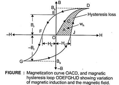
The hysteresis loss can be calculated by finding the area of the B-H curve.
To minimize hysteresis loss, the transformer’s core is made of Cold-Rolled Grain-Oriented (CRGO) Silicon Steel because this material’s magnetization curve area is less than that of other magnetic materials.
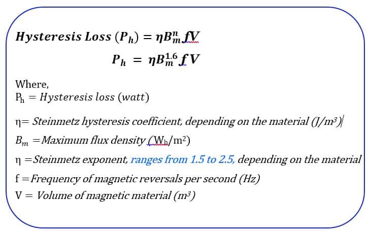
The hysteresis loss in the transformer core can be calculated using the following formula.
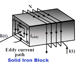
Eddy Current Loss
The flux that passes through the core induces a voltage of different magnitudes at various places on the surface of the core and the other conducting parts of the transformer.
Because of potential differences at various places on the core surface, the current setup in the core. These currents set up in the core are called eddy currents.
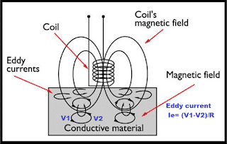
Because of eddy currents, heat loss equal to I2R loss occurs in the core.
The eddy current loss depends on the square of the current flowing in the upper part of the core and the resistance of the core material. The solid sheet of the iron block has less resistance because of the larger cross-section area.
The magnitude of the voltage induced in a solid block is higher, and as a result, the eddy current loss is higher in the solid iron block.
The eddy current in the transformer can be calculated using the following formula.
Dielectric Loss
Dielectric loss occurs in the insulation materials of the transformer due to the alternating voltage stress. This loss is usually minimal but becomes significant in high-voltage transformers.
Magnetostriction Loss
Magnetostriction loss occurs due to the physical expansion and contraction of the core material under the influence of the alternating magnetic field.
This results in mechanical energy loss, which is perceived as the characteristic humming sound of transformers.
How to Reduce No Load Losses in Transformers?
Reducing no-load loss in a transformer improves its efficiency and minimizes energy waste.
- Use cold-rolled grain-oriented (CRGO) silicon steel to reduce core losses.
- Consider advanced core materials like amorphous steel, which has lower hysteresis loss. Amorphous metal has very thin laminations (about 0.025 mm), reducing eddy current loss significantly compared to CRGO steel.
- Heat treatment (annealing) of the core improves its magnetic properties, reducing hysteresis loss.
- The core should be made of thin, insulated laminations to increase resistance and limit eddy current circulation.
- Using high-resistivity materials, such as silicon steel, reduces eddy currents.
- Use low-loss insulation materials like epoxy resin, Nomex, or transformer oil with high dielectric strength.
- Keep insulation dry and free from contaminants to avoid increased dielectric losses.
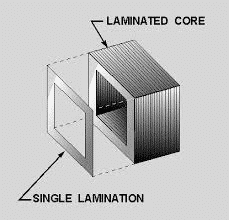
How does the thin laminated core reduce the no-load losses in a transformer?
The iron core is formed using several thin electrically insulated sheets called lamination to minimize the eddy current losses.
The area of the eddy current path gets reduced, and the losses decrease because of the decrease in induced voltage and increase in resistance.
The thin laminated sheet has higher resistance. The flow of eddy current in laminated sheets is given below.
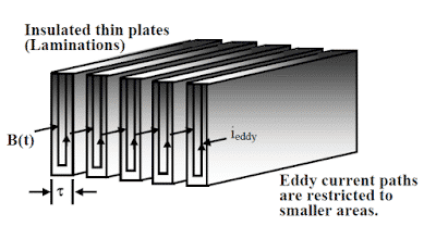
The current flowing in the sheet is equal to;
I = Potential difference of the EMF induced in laminated core/Resistance of the sheet.
As the thin sheet has higher resistance than the thick sheet, the current flowing through the thin sheet is very low compared to the current flowing through the thick sheet.
With the reduction in the magnitude of the eddy current in thin stamping, the eddy current loss reduces drastically. That is why the core of the transformer is made of thin laminated sheets.
Comparison: No Load Losses vs Load Losses in Transformer
Understanding the difference between core losses and copper losses in transformer operation is essential for improving efficiency.
No-load losses remain constant under rated voltage and frequency, while load losses increase with load current.
Difference between Transformer no load losses and load Losses
In a transformer, no-load losses refer to energy losses occurring in the core even when no current flows through the windings. These losses, also called core losses or iron losses, are caused by hysteresis and eddy currents due to the alternating magnetic field.
Load losses, on the other hand, occur when the transformer is supplying a load and are primarily due to the resistance of the windings, generating heat as current flows (I²R loss).
Key Differences:
- Cause of No-Load Losses – Result from hysteresis and eddy currents in the core.
- Cause of Load Losses – Arise from winding resistance and increase with the current.
- No-Load Losses are Constant – Remain relatively unchanged regardless of load.
- Load Losses are Variable – Increase proportionally to the square of the current.
Transformer no-load Loss Percentage
The no-load loss of a transformer typically ranges between 5% and 10% of its rated power.
These losses primarily result from hysteresis and eddy currents in the transformer core.
How to Calculate No-Load Losses in Transformer?
The open circuit test (also known as the transformer no load test) is used to determine the core losses in transformer and other no-load parameters.
This test is performed with one winding left open while the other is supplied with rated voltage and frequency.
Since there is no secondary current, the primary current is only responsible for core magnetization.
The power measured by the wattmeter during the open circuit test of transformer gives:
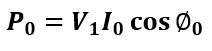
where:
- P0 = No-load power (W)
- V1 = Applied voltage (V)
- I0 = No-load current (A)
- cosϕ = Power factor at no-load
To learn more about how transformers are tested in practical scenarios, check out our detailed guide on Open Circuit and Short Circuit Test on Transformer.
Effect of Voltage and Frequency Variation on no-load Losses in Transformer
In addition to the dependency of eddy current on the stamping resistance, other electrical parameters like primary voltage and frequency also affect the eddy current loss.
The transformer is designed for a particular voltage and frequency. The change in supply voltage and frequency from the designed value will further lead to an increase in eddy current loss.
The transformer manufacturer gives a guarantee for iron loss for the operation of the transformer at rated voltage and frequency.
If the system voltage increases, the maximum flux density in the core increases, and consequently, the eddy current loss and hysteresis loss increase.
To protect the transformer from over-fluxing, the V/F ratio is measured, and the transformer can be switched off if the flux in the core reaches above the specified flux limit of the transformer.
Eddy current losses drastically increase with an increase in frequency if the voltage is also increased in the same proportion because the eddy current loss is proportional to the square of the frequency.
Generally, system frequency remains within the limit of rated frequency +/- 1.5 Hz; however, the electrical network rich in harmonics can lead to an increase in the eddy current loss.
With an increase in the frequency, the eddy current loss increases much more than the hysteresis loss because the eddy current loss is proportional to the square of the frequency. In contrast, the hysteresis loss is proportional to the frequency.
We can find the hysteresis loss by calculating the area of the hysteresis loop.
Thus, the transformer’s no-load losses are equal to the sum of the eddy current loss and the hysteresis loss.
The no-load losses of the transformer are constant for a rated voltage and frequency. Therefore, the no-load loss is also called a constant loss.
The no-load losses change if the transformer is operated above its rated flux density. Moreover, the increased flux density causes distorted secondary output voltage, and the transformer, if operated above the rated flux density, is apt to fail.
Therefore, over fluxing protection is employed to protect the transformer.
Variation in Transformer no-load losses with variation in voltage and or frequency
Let us understand how the hysteresis and eddy current loss get affected by changes in frequency and voltage. We will take four cases to study the no-load losses of transformers.
Case 1: Effect on no-load losses – When the frequency is increased/decreased, keeping voltage constant
The hysteresis loss is proportional to the frequency, and it increases with an increase in the frequency. However, the hysteresis loss remains almost unchanged. The reason is that the flux density in the core decreases in the same proportion as the increased frequency.
Similarly, the hysteresis loss should decrease with a decrease in frequency; however, it remains almost unchanged because of increased flux density in the core.
The eddy current loss is proportional to the square of the flux density and frequency. With an increase in the frequency, the eddy current remains unchanged because the product of B2m f2 remains unchanged as flux is proportional to the ratio of V/f.
With the decrease in frequency, the flux density in the core increases in the same proportion as the frequency decreases, and thus, the eddy current loss remains unchanged.
Case 2: Effect on no-load losses- When the voltage is increased/decreased, keeping the frequency constant
The hysteresis loss is directly proportional to the voltage and flux density. It increases with an increase in voltage.
The magnetic flux density is also proportional to the voltage. Thus, the hysteresis loss is proportional to the square of voltage if the frequency is kept constant.
Thus,
Hysteresis loss, Wh ∝ V2
Eddy current loss, We ∝ V3
Case 3: Effect on no-load losses – When the frequency is increased/decreased, and voltage is also increased/decreased in the same proportion
If the frequency is increased and voltage is also increased in the same proportion then the flux density in the core remains unchanged.
In this case, the hysteresis loss will increase proportionally to the increase of frequency.
The eddy current loss will increase in the square proportion of the increased frequency.
Case 4: Effect on no-load losses – When the frequency is increased/decreased, and voltage is also increased/decreased in different proportion
In this situation, the eddy current and hysteresis loss will increase or decrease because of the following reasons.
- Increase/decrease of frequency
- Increase/decrease of flux density
Related Articles: